ith the rapid development of the copper smelting industry, people’s demand for information in the copper smelting production process is undergoing profound changes both quantitatively and qualitatively. The original blast furnace monitoring method, which relies mainly on manual operation and reading, not only has low labour efficiency, but also requires manual recording and summary of various parameters. The workload is large and error-prone, and the existing blast furnace monitoring requirements cannot be met. At the same time, the rapid development and wide application of information technology, electronic technology and computer technology provide powerful technical support for blast furnace data acquisition automation. In such a large environment, it is an inevitable trend to realize the update of blast furnace monitoring technology and the replacement of equipment as soon as possible, and the development of electronic equipment for monitoring instruments, automation of test methods, and network transmission of data transmission. So, the embedded blast furnace real-time data acquisition system based on ARM microprocessor was born [1].
For the real-time data acquisition of copper liquid temperature in copper refining process, when contact type acquisition is adopted, since the copper refining furnace body often rotates, the collected thermocouples fixed on the furnace body are often replaced by high temperature copper liquid and high temperature flue gas. Immersion greatly affects the accuracy of collection and the life of thermocouples, so it is difficult to apply in actual production. When non-contact temperature measurement is adopted, the temperature of the high-temperature copper liquid must be measured through the high-temperature flue gas in the copper refining furnace, and the difference in the surface coverage of the copper liquid in the different processes in the copper refining furnace is different from the blackness [2]. The blackness of high-temperature flue gas is often in a changing condition, and non-contact measuring instruments cannot adapt to such changes, so the accuracy of non-contact measurement is greatly reduced, which will eventually lead to a decline in the performance of the control system. In addition, the copper refining furnace body There are restrictions on the opening, which is not convenient for the installation of non-contact measuring instruments. The non-contact measuring instruments are not only expensive, but also complicated to maintain, and the data is lagging. For many reasons, non-contact collection is also difficult to meet the production requirements.
The application of embedded system technology, function chain neural network and wireless communication technology in blast furnace copper liquid temperature data acquisition system greatly improves the accuracy and transmission efficiency of data acquisition. In this paper, an embedded application platform with simulated data acquisition, data communication and human-computer interaction is designed. At the same time, based on the blast furnace temperature control mechanism, the copper temperature data acquisition model and data pre-processing of copper refining furnace insulation process are established. At the same time, based on the theory of neural network, the parameter correction of adaptive function chain neural network learning algorithm is proposed. The blast furnace temperature control operation model is established by using fractional differential equations. The MATLAB software is used to simulate the copper liquid temperature.
Steady-state models in industrial process systems are often unknown, and the use of neural networks to identify nonlinear systems is an effective method. Among them, the BP network is the most widely used, but because of the slow convergence of the BP algorithm, it is easy to fall into local minima and other defects, which makes the online application difficult. Pao’s function-chain neural network overcomes the above shortcomings by using a non-linear extension of the original input mode as a single-layer forward network input. This single-layer network also has good nonlinear approximation capability and is therefore visible. Another effective way to identify steady state systems for industrial processes. In order to obtain a better identification effect, some systems use dynamic identification, and use the dynamic model to directly obtain a steady-state model. In some industrial processes, the output variable of the system has no online detection means, and it takes a long time to manually analyse and calculate [3]. It is difficult to obtain the dynamic information of the set point change to realize the dynamic identification of the system. Therefore, the steady state can only be used directly. Information identification steady state model. In order to reduce the set point of the system control quantity in the sample acquisition process and affect the normal operation of the actual system, an identification algorithm that can obtain better performance with only a small number of samples is needed.
\begin{equation}\label{eq1}\tag{1} Y = F\left( X \right) \end{equation}Where F is a nonlinear function, \(Y \in R^{m},X \in R^{m}\).
The function chain neural network is used for identification. Firstly, the input mode should be appropriately nonlinearly extended in a linear independent manner, and then the constructed single-layer network is trained. The FL network learning algorithm is like the BP algorithm, and the d rule is adopted. The goal is to minimize the total error of the actual output from the expected output (assuming the number of samples is \({\rho}\)), i.e.: \begin{equation}\label{eq:FD2}\tag{2} \left. E = \frac{1}{2{\rho}}{\sum\limits_{i = 1}^{{\rho}}{\sum\limits_{j = 1}^{m}\left( {T_{ij} – O_{ij}} \right)^{2}}}\rightarrow\text{min} \right. \end{equation}
Among them, \(T_{ij}\) and \(O_{ij}\) are the jth teacher signal and output signal of the i-th group sample respectively, and the weight adjustment adopts the gradient descent method. Because the FL network is a single layer, the convergence is extremely fast and does not fall into the local minimum point. In fact, the generalization ability of the network can be improved by making the output mode of the network insensitive to small changes in the input, that is, while (2) is established, it is desirable that \(\sum\limits_{k = 1}^{r}\left( {\partial E/\partial x_{k}} \right)^{2}\) is as small as possible. Can be
\begin{equation}\label{eq:FD3}\tag{3} E' = \frac{1}{2}{\sum\limits_{i = 1}^{{\rho}}{\sum\limits_{j = 1}^{m}\left( {T_{ij} – O_{ij}} \right)^{2}}} + \frac{1}{2}\beta{\sum\limits_{i = 1}^{{\rho}}{\sum\limits_{j = 1}^{r}\frac{\partial\left( {T_{ij} – O_{ij}} \right)^{2}}{\partial x_{ik}}}} \end{equation}
Order: \(O_{ij} = f_{ij}\), weight \(w_{ij}\) and threshold \(\theta_{j}\) learning algorithm: \begin{equation}\label{eq:FD4}\tag{4} \begin{cases} \begin{array}{l} \frac{\partial E^\prime}{\partial w_{ik}} = – x_{k}\sum\limits_{i = 1}{{\sum\limits_{j = 1}{\left( {T_{ij} – O_{ij}} \right)f^\prime_{ij}}}} \\\;\;\;\;\;\;\;\;\;\;\;\; + \beta\left( w_{ik}\sum\limits_{i = 1}{\sum\limits_{j = 1}{\left( {T_{ij} – O_{ij}} \right)^{2}f^{2}_{ij}}}\right.\\\;\;\;\;\;\;\;\;\;\;\;\; + x_{k}\sum\limits_{k}w_{ik}^{2}\sum\limits_{i = 1}\sum\limits_{j = 1}\left( {T_{ij} – O_{ij}} \right)\\\;\;\;\;\;\;\;\;\;\;\;\; \times\left.f^\prime_{ij}\left( {\left( {T_{ij} – O_{ij}} \right)f^{\prime\prime}_{ij} – {f^\prime_{ij}}^{2}} \right) \right) \\ {\frac{\partial E'}{\partial\theta_{j}} = – {\sum\limits_{i = 1}{\sum\limits_{j = 1}{\left( {T_{ij} – O_{ij}} \right)f'_{ij}}}}} \\ {\Delta w_{ik} = – \eta\frac{\partial E'}{\partial w_{ik}} + \alpha\Delta w_{kj}} \\ {\Delta\theta_{kj} = – \eta\frac{\partial E'}{\partial w_{ik}} + \alpha\Delta w_{kj}} \\ \end{array} \end{cases} \end{equation}
Where \(\eta\) is the learning factor; \(\alpha\) is the smoothing factor; \(\beta\) is the weighting factor. When the stimulus function takes the sigmoid function [4]: \begin{equation}\label{eq:FD5}\tag{5} \begin{cases} \begin{array}{c} {f_{ij} = \frac{1}{1 + e^{- ne^{t}}} = \frac{1}{1 + e^{- {({\sum{w_{jk}xi_{k} + \theta_{j}}})}}}} \\ {f'_{ij} = f'_{ij}\left( {ne^{t}} \right) = \left( {1 – O_{ij}} \right)O_{ij}} \\ {f''_{ij} = f''_{ij}\left( {ne^{t}} \right) = \left( {1 – O_{ij}} \right)\left( {1 – 2O_{ij}} \right)O_{ij}} \\ \end{array} \end{cases} \end{equation}
When the weighting factor \(\beta = 0\) is used, it is the original algorithm.
Due to the complexity of the actual production environment, in order to establish a copper temperature data acquisition model for the oxidation process of copper refining blast furnace, the following assumptions are made: 1) The flame in the furnace and the heating condition of each heating surface are evenly distributed in space; 2) the flame is radiated and convection to the furnace copper melt and heat transfer in the furnace; 3) the amount of change in the heat loss of the exhaust air and the heat loss to the surrounding environment during the oxidation process; 4) taking into account the high temperature hot smoke density in the furnace \({\rho}_{y}\) is small, ignoring its weight change, that is, \({\rho}_{y} = const\); 5) The high temperature flue gas temperature only changes at the start and end points of the sampling period interval \(\left( {n\tau_{0},\left( {n + 1} \right)\tau_{0}} \right)\), but remains unchanged during the sampling period interval \(\left( {n\tau_{0},\left( {n + 1} \right)\tau_{0}} \right)\).
Firstly, the energy balance equation in the furnace of a copper refining blast furnace. 1) Composite heat exchange between furnace flue gas and scum of surface of molten copper. According to the process mechanism in the furnace of the oxidation process of the copper refining blast furnace, the convection and radiant heat of the high-temperature flue gas absorbed by the surface scum of the crude copper melt in the furnace of the copper refining blast furnace can be determined by the following formula [5]: \begin{equation}\label{eq:FD6}\tag{6} Q_{r} = C\sigma_{0}\varepsilon_{gwm}F_{m}\left\lbrack {\left( {\theta_{g} + 273} \right)^{4} – \left( {\theta_{z} + 273} \right)^{4}} \right\rbrack \end{equation} where \(C\) is the correction coefficient considering the convection of high temperature flue gas, \(C = 1.03 – 1.08\); \(\sigma_{0}\) is the Stefen-Boltzmann constant, and \(\sigma_{0} = 5.67 \times 10^{- 8}W/\left( {m^{2} \cdot k^{4}} \right)\); \(\sigma_{g}\) is the temperature of the high temperature flue gas, \(^\circ\)C; \(\sigma_{z}\) is the average temperature of the scum on the surface of the blister copper melt, \(^\circ\)C; \(\varepsilon_{gwm}\)is the comprehensive emissivity of the high temperature flue gas and the inner wall of the furnace against the surface scum of the blister copper melt. \(\varepsilon_{gwm}\) is determined by: \begin{equation}\label{eq:FD7}\tag{7} \varepsilon_{gwm} = \frac{\varepsilon_{g}\varepsilon_{m}\left\lbrack {1 + {\phi}\left( {1 – \varepsilon_{g}} \right)} \right\rbrack}{\varepsilon_{g} + {\phi}\left( {1 – \varepsilon_{g}} \right)\left\lbrack {\varepsilon_{m} + \varepsilon_{g}\left( {1 – \varepsilon_{m}} \right)} \right\rbrack} \end{equation} where \(\varepsilon_{g},\varepsilon_{m}\) is the blackness of the scum on the surface of the high temperature flue gas and the blister copper melt; \({\phi}\) is the angular coefficient of the scum of the inner wall of the combustion chamber to the surface of the blister copper melt, \({\phi} = F_{m}/F_{w}\); \(F_{m}\) is the surface area of the scum of the blister copper melt surface , \(m^{2}\) ; \(F_{w}\) is the effective radiation area of the inner wall of the furnace, \(m^{2}\).
2) The blister copper melt heat balance equation. The heat balance equation of the blister copper melt in the blister copper refining furnace is: \begin{equation}\label{eq:FD8}\tag{8} Q_{r} = \eta D_{c}c_{pc}\theta'_{ce} \end{equation}
In the formula, \(\eta\) is the radiant heat loss coefficient caused by the immersion of the fused copper melt into the environment. According to the metallurgical calculation, \(\eta = 0.95 – 0.98\); \(D_{c}\) is the mass of the blister copper melt in the furnace of the copper refining furnace, kg; \(c_{pc}\) is the specific heat capacity of the blister copper melt in the furnace of the copper refining furnace, kJ/(kg\(\cdot\)\(^\circ\)C); \(E\) is the average temperature change of the blister copper melt, \(^\circ\)C/s, due to \(\theta_{ce} = \theta_{c} – \Delta\theta_{0}\). \(\Delta\theta_{c0}\) is the difference between the average temperature of the copper surface and the average temperature of the copper solution, and considers \(\Delta\theta'_{c0}\) to be a constant value: \(\theta'_{ce} = \theta'_{c}\). Secondly, the copper liquid temperature data acquisition model of the oxidation process was established. Connecting with (7), (8), (9) formulas, can get
\begin{equation}\label{eq:FD9}\tag{9} A\left( {\theta_{g} – \theta_{z}} \right) = \frac{d\theta_{c}}{d\tau} \end{equation} where \(A = 4C\varepsilon_{g}F_{m}\left( {\theta_{H} + 273} \right)^{2}/\eta D_{C}c_{pc}\) and \(\theta_{c2}\) are a fixed value nearby \(\left( {\theta_{c} + \theta_{\text{g}}} \right)/2\), taking \(\theta_{\text{H}} = 1250\) \(^\circ\)C; \(\tau\) is time. By integrating the equation (10) over the sampling period interval \(\left( {n\tau_{0},\left( {n + 1} \right)\tau_{0}} \right)\), we can get: \begin{equation}\label{eq:FD10}\tag{10} \frac{y_{n + 1} – x_{n + 1}}{y_{n} – x_{n}} = e^{- A\tau_{0}}\end{equation}
Where \(\tau_{0}\) is the sampling period, \(x_{n},x_{n + 1}\) is the measured value of the nth and n+1 copper liquid temperatures, respectively; \(y_{n},y_{n + 1}\) is the measured value of the high temperature flue gas temperature after the nth and n+1th filtering processes, respectively. In the case that the sampling period \(\tau_{0}\) is constant, the right side of the formula (11) is also a constant, and \(x_{1} = \theta_{0},y_{1} = \theta_{0c},\left( {y_{n} – x_{n}} \right)\) is an equal ratio series, and finally the copper liquid temperature data acquisition model of the oxidation process is obtained as follows: \begin{equation}\label{eq:FD11}\tag{11} x_{n + 1} = y_{n + 1} – e^{- A{({n + 1})}\tau_{0}}\left( {\theta_{0} + \theta_{c}} \right)\end{equation}
Where: \(\theta_{c0}\) is the initial measured value of the blister copper melt temperature, and \(\theta_{0}\) is the initial measured value of the high temperature flue gas temperature.
1) Acquisition and transmission function: This system is a blast furnace device, and the main copper temperature data is collected, displayed and transmitted in real time. The type of data collected is an analog signal. 2) Curing operation mode function: The normal operation of the system is completely controlled by the fixed button fixed operation program. When the system is started, it will enter the parameter configuration before starting the acquisition, including setting the acquisition channel, gain, channel and other contents of the analog signal. After the setting is completed, the acquisition process is started. The entire acquisition process is completed automatically, without manual intervention, and the collected data is automatically processed and uploaded to the host computer. 3) Setting change function: Users can change the system settings to adapt to changes in test objects or changes in test requirements, such as: increase or decrease of test channels, changes in communication protocols, and changes in sampling rates [6].
1) Realize single-channel data acquisition; 2) sampling accuracy \(\leq\)0.01%; 3) realize multiple data communication methods; 4) realize flexible configuration of upper layer software; 5) temperature collection range 0~1600\(^\circ\)C; 6) working environment: work Temperature: -30\(^\circ\)C ~ 70\(^\circ\)C (the liquid crystal display operating temperature is -20\(^\circ\)C ~ 55\(^\circ\)C, when the test is required for higher environmental requirements, the LCD screen should be removed); storage temperature: -45\(^\circ\)C ~ 85\(^\circ\)C; working humidity: 90% \(\pm\) 3%; storage humidity: 20% -95%; vibration, shock and electromagnetic compatibility to meet the requirements of the blast furnace environment.
1) CPU core module: This module is mainly composed of CPU and its peripheral circuits, which constitute the main control circuit of the whole system. The CPU is the core of the entire test system. It is responsible for coordinating and managing each module, including analysing, processing, displaying and storing the collected data; responsible for scheduling and decision-making between tasks. In this system, we chose the 32-bit high-performance embedded processor LPC2114, which is a highly integrated embedded processor, integrated with ARM7TDMI CPU core, 128k cache memory, the maximum frequency can reach 66MHz, and low Power consumption is optimized for the purpose. Suitable for this system [7].
2) Analog circuit: This module includes the conditioning circuit for the input signal. The conditioning circuit mainly amplifies and filters the input analog signal to obtain a value that satisfies the input range of the analog-to-digital conversion circuit. The system design uses PGA204 circuit, and uses LPC2114 built-in A/D converter to send the signal obtained by temperature sensor application circuit and signal amplifying circuit to LPC2114 built-in A/D converter for conversion.
3) System storage module: System storage is mainly composed of 3 parts, on-chip Flash, E2PROM. Among them, on-chip Flash is used to store the system start-up program, operating system and application code. E2PROM is used to store personal and physiological data of users. The main control module expands a 1K E2PROM chip AT2401 on the I2C bus of the LPC2114.
4) System input and output module: The input and output module are to realize the communication and dialogue between the user and the computer’s two “intelligent systems”. It provides users with rich and friendly operation interface and human intervention function through buttons and liquid crystal display devices. Designed to provide reliable support for the user’s correct decision making[8].
5) Communication module: This module consists of 3 parts of circuit, modem, JTAG circuit, infrared circuit and USB interface circuit. The JTAG circuit is used to download the debugger. The USB interface is used to transfer the collected data to and from the PC. The PDIUSBDI2 used by the USB chip conforms to the USB1.1 protocol and can achieve a transmission rate of 1.2 Mbytes/second. It is suitable for transmitting a large amount of data; the infrared circuit is used to Handheld portable device communication for the PDA; Modem is used to connect to the network. The system block diagram is shown in Figure 1.
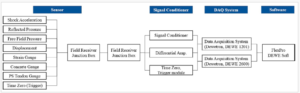 Figure 1: Block diagram of embedded blast furnace real-time data acquisition system
Since the LPC2114 has 10 A/D converters built in it, the A/D conversion circuit design in this system sends the signals obtained by the temperature sensor application circuit and the signal amplification circuit to the A1N3 channel of the LPC2114 built-in A/D converter. The actual temperature value is obtained after the conversion. Here, the platinum-iridium 13-platinum thermocouple is selected. From the index table, the relationship between the potential value and the temperature increases monotonically. The data in the table is 0~1600\(^\circ\)C, and the corresponding potential range is 0~18849\(\mu\)V. Taking into account the sampling requirements of ARM, linear amplification is required for the thermocouple, which is amplified by 100 times and its potential output range is 1.8849V, which meets the sampling requirements and measurement range requirements.as shown in Figure 2.
 Figure 2: Schematic diagrams of the front-end simulation system.
In the data acquisition system, the front-end gain circuit is composed of PGA204. The PGA204 is a low cost, versatile, programmable gain instrumentation amplifier. At the same time, it provides very good accuracy. The gain can be selected numerically: the PGA204 gains are 1x, 10x, 100x and 1000x. The gain selection is made via address lines A0 and A1 that are compatible with TTL or CMOS levels. The internal input protection can withstand voltages up to \(\pm\)40V at the analog input without any damage. PGA204 is commonly used in data acquisition systems, general purpose analog boards, and medical instruments. It is available in 16DIP and SOL-16 packages [9]. The chip’s operating temperature range is -40\(^\circ\)C – +85\(^\circ\)C. The internal structure of the PGA204 chip is shown in the following Figure 3:
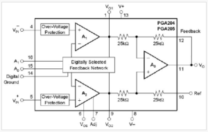 Figure 3: PGA204 chip internal structure
The main control system adopts the modular structure design idea, and divides the equipment into main control modules and various functional modules. There is a uniform or specific interface between the main control module and each functional module. Users can choose different function modules according to different needs. Various types of data can be transmitted simultaneously without interfering with each other. At the same time, other functional modules, such as optoelectronic communication modules, can be extended according to the needs of the process. This design structure is not only convenient to use, but also beneficial to the future upgrade of the system. The main control module is mainly responsible for human-computer interaction, communication with function modules, data storage, data transmission and other functions. The user operates the function module and other functions of the system by controlling the main control module. The data is stored in the main control module. Then, the main control module can dial the Internet through the telephone line or access the networked PC through the USB port to send data to the server or communicate with the handheld computer through the infrared module. Such three data transmission methods can meet the needs of most users[10]. As shown in Figure 4.
 Figure 4: Structure of the main control module
The communication of the main control module is divided into three parts: USB, UART0, and UART1. UART0 is used to communicate with various functional modules, including the infrared communication module. Except for the infrared module, an I/O port (P0.25) is required to perform the control signal as the selected baud rate. All other modules only need to be connected with UART0. Connect the three wires of TXD0, RXD0 and GND. UART1 is used to communicate with Modem. The external Modem interface is RS-232 interface. Therefore, TXD1 and RXD1 of UART1 need to be level-converted through MAX232 and connected to Modem.
From the above copper liquid temperature acquisition model establishment process, it can be known that the copper liquid temperature acquisition model is based on the assumption that the high temperature flue gas temperature satisfies the assumption, but the actual situation is that there is a nonlinear relationship between the copper liquid temperature and the flue gas temperature. If this copper liquid temperature data acquisition model is directly used, first, the accuracy is not high, and second, when the environmental conditions change, the characteristics of the acquisition model will change. Therefore, in order to prevent the model parameters during the use of copper liquid data collection, The drift is based on the adaptive technique of the functional chain neural network to correct the copper temperature data acquisition model online. It is assumed that the corrected copper liquid temperature acquisition output value can be described by a power series n-degree polynomial:\[\label{eq:FD12} X\left( x_{i} \right) = c_{0} + c_{1}xi + c_{2}x_{i}^{2} + … + c_{n}x_{i}^{n}\]
Where \(x_{i}\) is the ith acquisition output value of the copper liquid temperature. The value of n is determined by the accuracy sought. In general, when n=3, it has higher precision. Therefore, if the system takes n=3, then:\[\label{eq:FD13} X\left( x_{i} \right) = c_{0} + c_{1}xi + c_{2}x_{i}^{2} + c_{3}x_{i}^{3}\]
Figure 5 shows a functional chain neural network. In the Figure, \(W_{j}\left( {j = 0,1,2,3} \right)\) is the connection weight of the network. The number of connection weights is the same as the order of the inverse nonlinear polynomial, i.e. j=n. Assuming that the neurons of the neural network are linear, the output value \(X_{i}^{est}\left( k \right)\) expression of the function chain neural network is
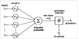 Figure 5: Schematic diagram of the function chain neural network
\[\label{eq:FD14} X_{i}^{est}\left( k \right) = {\sum\limits_{j = 0}^{2}{x_{i}^{j}W_{j}\left( k \right)}}\]
Where \(W_{j}\left( k \right)\) is the weight of the kth step, \(W_{j}\left( {k + 1} \right) = W_{j}\left( k \right) + \eta_{i}e_{j}\left( k \right)x_{i}^{j}\), \(e_{j}\left( k \right) = x_{i} – X_{i}^{est}\left( k \right)\), and \(\eta_{i}\) are the learning factors, and its choice affects the stability and convergence speed of the iteration. Let \(\eta_{i} = 1 – k/M\): M be the maximum number of iterations. The neural network toolbox is implemented with the function maxlinlr.as shown in picture 5. (Figure 5)
Based on the actual production situation of a 350t copper refining blast furnace in a smelter, the reliability of the on-line data acquisition model of copper in the furnace was studied. Table 1 shows the results of the copper liquid temperature expected value \(\theta_{c1}\) and the copper liquid temperature data acquisition value \(\theta_{c2}\) in the 1# copper refining furnace during the heat preservation process.
| temperature | time | |||
|---|---|---|---|---|
| 8:40 | 9:00 | 9:20 | 9:40 | |
| \(\theta_{c1}\) | 1123 | 1129 | 1135 | 1126 |
| \(\theta_{c2}\) | 1125 | 1127 | 1136 | 1127 |
It is found from Figure 6 that after the correction by the function chain neural network, the error of the copper liquid temperature data acquisition model converges quickly, and the copper liquid temperature can be collected in real time.
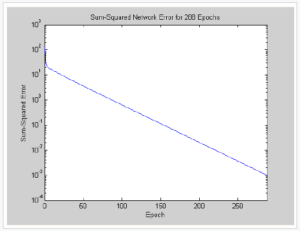 Figure 6: Error record during network training
1) Ambient temperature: 20 \(^\circ\) C; relative humidity: 65%; atmospheric pressure: 101 KPA; no strong magnetic field, strong electromagnetic radiation, no obvious strong vibration; no obvious dust, corrosive gas. 2) Power supply. Voltage 12V \(\pm\) 1%; ripple <0.1%; 3) Test equipment. Power supply, standard signal source, oscilloscope, multimeter, personal computer, ARM debugging development software ADS1.2 and simple production JTAG emulator.
The power circuit, crystal oscillator circuit and reset circuit are relatively simple. The power output can be measured directly with a multimeter. The output of the passive crystal can be observed with an oscilloscope. The RESET terminal of the reset circuit outputs 3.3V when the button is not pressed. It becomes low when the button is pressed, and returns to the high level after the button is released. The power circuit, crystal oscillator circuit and reset circuit are the basic working conditions of the whole system, and they should be guaranteed to work normally. The test plan design of the peripheral device is mainly to test three units – data acquisition unit, I2C storage unit and data transmission unit. Solution design: first start the data acquisition unit, program select AD channel 3, add a 1V voltage to the channel pin (short the input terminal to the ground terminal), start AD conversion, read AD data, and then store it in the data storage unit. Then, the data is read into the computer through the USB interface of the communication unit, and finally the calculation is performed to obtain the resolution of the A/D. The real-time operating system is not running during the peripheral device test. Instead, after the ARM startup program runs, it jumps directly into the program of each unit part to be tested, and implements the functional test of the peripheral test unit.as shown in Table 2.
| No. | Test items | result |
|---|---|---|
| 1 | A/D sampling accuracy | 10 digits |
| 2 | A/D sampling rate | 1Msps |
| 3 | USB communication | This function |
| is implemented | ||
| 4 | Modem communication | This function |
| is implemented | ||
| 5 | Infrared communication | This function |
| is implemented | ||
| 6 | LCD display | This function |
| implements some | ||
| functions | ||
| 7 | I2C storage | This function |
| is implemented |
Based on the differential equation model established by the physical characteristics of the embedded blast furnace temperature control system, the mathematical model of the copper liquid temperature acquisition system is established based on the mechanism. Combined with the neural network and MATLAB software, the parameter correction of the adaptive function chain neural network learning algorithm is proposed. It makes the copper liquid temperature acquisition system better adapt to the temperature change. The simulation results show that the adaptive function chain neural network learning algorithm parameter correction is effective, with adaptive and self-learning functions.