The construction industry is an important pillar of China’s national economy, and the relationship between the national economy and people’s livelihood is very close [1]. 40 years of reform and opening up, the proportion of the construction industry in the national economy has been increasing [2]. At present, China’s construction industrialization has entered a new stage of development, the 18th National Congress of the Communist Party of China to develop “new industrialization, informatization, urbanization, agricultural modernization”, and in the report of the 19th CPC National Congress re-emphasized the promotion of the synchronous development of the above “four” [3]. In the 2016-2020 Outline for the Development of Information Technology in the Construction Industry, the goal of comprehensively improving the level of information technology in the construction industry was set out, emphasizing the ability to promote the integrated application of information technology such as BIM, big data, intelligence, mobile communications, cloud computing, and the Internet of Things in the design, production, transportation, assembly, and the whole life cycle of the assembled building [4].
The BIM technology has a significant advantage in the assembly building, providing a more comprehensive view of the parties involved in the process, and the collaboration between different stakeholders in the process, greatly reducing the amount of time invested in design, component, construction, and operational projects, and is more conducive to the implementation of cost estimates and resource allocation decisions. However, although there are many advantages in the application of BIM technology in the general life cycle of the assembly, the main idea is that there is a difficulty in effectively communicating with different software programs developed by different suppliers, and the lack of training may lead to the difficulty of adapting to too complex user interfaces without the experience of BIM.
In order to improve the overall quality of the construction project, we must start from the structural design of the assembly building, in order to protect the overall construction quality of the construction project [5]. The construction unit in the structural design of the assembly building should be considered from many aspects, in order to ensure that the structural design of the building can meet the requirements of the people and construction standards [6]. Designers must pay attention to several key points in the structural design of assembly buildings to ensure the quality of structural design, so as to improve the overall quality of the building [7]. Components are the basic elements of assembly buildings, with a large number, high molding degree, morphology and other characteristics [8]. In assembled buildings, by accurately identifying components and obtaining component location information, it is possible to rationally organize production and construction and optimize resource allocation [9], while relying on manual methods is not only difficult to track and locate all the components and supervise and manage them throughout the entire project, but also very prone to component loss, difficulty in locating and installing incorrectly, which can increase the project man-hours and costs [10]. Therefore, component tracking and positioning requires the support of intelligent and information technology to minimize manual intervention [11]. In addition, component tracking and positioning is a dynamic process, each stage of the component state, location and positioning accuracy are not the same, and is closely related to the content of the work at each stage [12]. Therefore, appropriate data acquisition technology is needed to realize real-time tracking and positioning and monitoring of components, and to obtain and process the spatial location information of components in a timely manner [13].
The quality assessment of modular components before shipment mainly relies on manual measurement, which is labor-intensive, time-consuming, and inaccurate, etc. Son, R. H. and Han, K. proposed a model of 3D scanning planning method for modular components based on laser scanning of modules, i.e., automatically scanning and outputting results that meet the user’s requirements given CAD or BIM, scanner attributes, and user’s requirements [14]. Chang, C. et al. proposed an optimization model for the production of concrete assembly building components with the help of DDE algorithm, POX cross-evolution method, and dual genetic chromosome coding model and active scheduling decoding method based on the rich variety of assembled building components and high production cost, as well as the characteristics of the production of concrete assembly building components [15].
In addition, A, V. N. and B, R. S. used RFID technology to scan and identify the assembled building components, which were color coded and outputted by CAD model, during the simulation process with LEGO, the RFID tags were installed in the assembled building components and taken by the different parts of the supply chain from the production to the construction, and the experiments showed that this system helped to reduce the cost and save time [16]. Zhang, K. et al. applied convolutional neural network in the field of tracking and localization in the field of assembled building components, and proposed a new method based on the combination of multi-tag classification loss equation modeling and probabilistic search algorithm, and proposed a new method based on the combination of multi-tag classification loss equation modeling and probabilistic search algorithm. K. et al. applied convolutional neural network to tracking and localization in the field of assembly building components, proposed a new method based on the combination of multi-label classification loss equation modeling and probabilistic search algorithm, and improved the positive incentive probability score in training, and simulation experiments showed that the method helps to realize intelligent localization of assembly building components [17].
The application of BIM technology is an important direction for future construction. Cai, H. combined BIM technology with artificial intelligence, and established the D-H rule model of construction error detection, and provides a new direction for the trajectory calibration of construction structure [18]. Xie, P. et al. proposed an integrated model for the station engineering management and wind risk assessment based on BIM-RF. The paper used the revit software to realize the 3D parameterization of the construction structure, and the risk probability analysis was carried out by combining monte carlo simulation [19].
This study realizes the centralized management of component information by constructing an assembly building database and information management platform. Meanwhile, Deep Sort multi-target tracking algorithm and BeiDou high-precision differential positioning technology are applied to improve the accuracy and efficiency of component tracking and positioning. Finally, the effectiveness of the proposed method is verified through experiments to ensure its reliability and efficiency in practical applications.
The advantages of assembly building development are short construction period, high productivity, high utilization of resources, protection of the environment, in line with the concept of sustainable development of society, and its construction is characterized by many components, complex processes, difficult and dynamic changes in information management. However, in the actual construction process, it is difficult to transfer the component status information, difficult to locate the components, and it takes a long time to check them one by one manually according to the drawings. Exploring the tracking and locating of structural components in assembled buildings can effectively solve the problem of transferring the component status information in assembled structure construction, and improve the efficiency of the construction. This chapter mainly focuses on the relevant process of assembly building to provide the basis for realizing the tracking and positioning of structural components of assembly building.
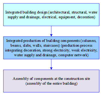
The Technical Standard for Assembly of Concrete Structure Buildings defines an assembled building as a building in which the main parts of the structural system, the peripheral protection system, the equipment and piping system, and the interior system of the building are integrated and assembled using prefabricated parts and components. The concept of assembled building is shown in Figure 1, which in layman’s terms means that the building components (component parts) such as columns, beams, slabs, internal and external walls, staircases, balconies, etc. are prefabricated in a modernized factory, and then transported to the construction site site, and become assembled buildings after rapid assembly.
Assembled buildings are mainly characterized by the following features:
The main components are prefabricated in the factory or on-site, and can be mechanically lifted at the same time as the on-site professional construction, which can shorten the construction cycle and reduce the amount of wet work on-site to facilitate winter construction.
Component prefabrication and traditional pouring is different in the fixed template plane construction instead of the traditional three-dimensional cross-cutting construction, to a large extent, to improve the production efficiency and product quality is reliable, safe and green, and can effectively reduce construction costs.
Prefabricated components are highly integrated, in the production process of components can be used in the vertical molding process or reverse once the molding process, such as thermal insulation, and other special requirements of the components and concrete wall panels in the factory to complete the production.
Can effectively reduce construction waste, through the use of durable, repeatable or recycled materials to extend the life cycle of materials, reducing material and resource loss.
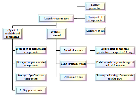
Assembly building foundation engineering construction and traditional cast-in-place building is basically the same, the process of the main structural engineering, such as the production of prefabricated components, transportation, lifting, support and reinforcement of prefabricated components, after pouring parts of the concrete pouring, maintenance. The smooth and safe construction process of assembly building construction is a key step to ensure safe construction, the specific construction process shown in Figure 2. The carrier of assembly building construction is prefabricated components, and the common main prefabricated components are stacked beams, stacked panels, load-bearing walls, lightweight partition walls, exterior wall panels, and prefabricated stairs. Taking prefabricated components as the object of construction stage division, the assembly building construction process can be divided into four stages: production of prefabricated components, transportation of prefabricated components, storage of prefabricated components, and lifting of prefabricated components. Taking the engineering process as the object of construction stage division, the assembly building construction process can be divided into three parts: foundation project, main structure project, and decoration project.
Assembled building is an important means to promote the construction industry to carry out industrial structural adjustment and reform, low-carbon and green development, with outstanding features such as design standardization, production industrialization, construction assembly, decoration integration, operation intelligence, management informationization and so on. It also has obvious social, economic and environmental benefits. Compared with traditional cast-in-place buildings, it has many advantages such as high efficiency, economy and environmental protection.
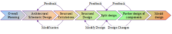
The design process of assembly building is shown in Figure 3, which includes overall planning design, monolithic building design, construction drawing design, but also component deepening design, mold deepening design and so on. Assembly building in the design stage should not only take into account the elements of conventional building design, but also give full consideration to the industrialization of the building, standardization of the implementation of feasibility. This requires assembly building in the design stage, and structure, equipment, decoration and other professional communication in advance, the production, transportation, construction and other construction processes to do advance planning and design.
Modularized design of prefabricated components is a guarantee for improving the refinement and accuracy of assembled buildings, as well as a prerequisite for realizing the industrialization and standardization of construction. Modular design effectively improves the construction efficiency of assembled buildings, achieves the demand for different window opening sizes through the combination of molds, produces components with different specifications of modulus, improves the production efficiency, reduces the cost, and improves the construction quality of the overall building.
Component production and processing is a process unique to assembled buildings, centralized in a fixed place, the manufacturing process is not affected by the weather, the production process is linear, and the efficiency of component production is high. Component production process is mainly mold design \(\mathrm{\to}\) steel pre-embedded \(\mathrm{\to}\) component production \(\mathrm{\to}\) quality testing \(\mathrm{\to}\) component transportation \(\mathrm{\to}\) component lifting \(\mathrm{\to}\) component storage and so on. The specific process mainly includes the following steps:
Mold design. According to the wall size combination formed by the mold should be in line with the wall specification size, the joints are tight, the wall sleeve and hole position in advance of the positioning design, to ensure that the concrete pouring does not occur displacement.
Pre-embedded steel. Pre-embedded parts, connectors and sleeves in the rebar fixed firmly, together with the reinforcing components into the mold, into the mold, pay attention to the position of the reinforcing steel skeleton and pre-embedded deviation, need to be within the allowable value.
Production of components. Before pouring concrete, clean the mold and steel surface debris, brush mold release agent.
Quality inspection of components. The production process is the detection of hidden works of reinforcement and embedded parts, prefabricated components after the completion of the quality test mainly include components of concrete strength, embedded parts sampling inspection.
Transportation of components. Reasonable choice of transportation vehicles, research transportation routes, real-time monitoring of transportation and loading and unloading vehicle process.
Lifting of components. Prefabricated components lifting process is a dynamic force process, to keep the prefabricated components rise at a uniform speed, to avoid swaying from side to side uneven force, resulting in cracks in the components, or even damage.
Storage of assembly components. The storage of prefabricated components of assembly building is mainly distributed in two places, one is the prefabricated components are stored in the processing plant after processing in the factory, and the other is stored in the construction site.
Prefabricated components, as the basic elements of assembly buildings, are characterized by their large number, good molding degree and similar shape. When constructing an assembly building, through the application of information technology, identifying prefabricated component information and obtaining the location of the components, the construction can be scientifically and reasonably organized and resources can be deployed. This can well avoid the situation that components are easy to be lost, the location is not clear, and there are problems in assembly in the traditional construction process. The tracking and positioning management of prefabricated components is dynamic and needs the strong support of information technology. This chapter mainly focuses on the logistics level to realize the tracking and positioning of structural components of assembled buildings, with a view to better realizing the resource deployment of assembled buildings.
The assembled building database is the “brain” of the component tracking and localization technology chain, which creates and stores all the information of the components. In terms of the relationship between individual components and the building as a whole, the assembly building database mainly includes two types of component data, one is the general data of components, such as component type, component category code, component size, material, performance and other information, which is the inherent data of components. The other type is the project data of the component, such as the code, position, status, and assembly level of the component in the project, and this type of data exists depending on the specific project. Among these data, information such as component type, component category number, component size, component project code, component location, component status, component assembly level, etc. are directly related to the tracking and localization of components.
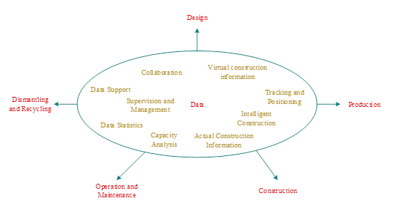
The assembly building information management platform is an integrated management system for storing, maintaining and managing the building data resource base, improving information model processing capability, providing data interfaces and multi-party collaborative design for specialized applications, and unifying the management of the project’s full life cycle information, among other uses. The main functions of the assembly building information management platform, as shown in Figure 4, are the key to tracking and positioning prefabricated components throughout the entire assembly building process, enabling all project participants to share and collaboratively manage the spatial information of the components without any obstacles, and improving the operability of real-time tracking and positioning of the components during the entire life cycle.
The assembly building information management platform mainly relies on the support of the assembly building database and data collection technology. The assembly building database is the core of the information platform, and the data collection technology is able to obtain the spatial information of the components in a timely manner and upload it to the information platform to realize the unified management of the project.
In the process of assembly building information management, the data security problem has a profound effect on the design of the whole construction project. Only by ensuring the safety of the data can the value and function of the bim model be developed. First, the access to the folder, the modification authority, the ability to specify the folder access and the modification of the folder, not qualified personnel, can’t access the folder without authorization, and it is more difficult to change the contents of the folder at will, and then provide a guarantee for the security of the file and the number of files. Second, specify the qualification level of the folder access. For the basic information data, the important information of the construction project design, the important notification information, the folder of the information information relevant to the design meeting, the access qualification can be divided into two kinds: read-only and written. The professional responsible staff and design staff only allow read-only permissions, and the director of the whole project has the ability to write permission.
In this paper, Deep Sort algorithm is used to complete the tracking and matching of vehicles transporting structural components of assembled buildings. Sort algorithm combines the Hungarian algorithm and Kalman filter, which is a simple real-time multi-target tracking algorithm that creates new IDs (and destroys old IDs) according to the entry of new targets (and the departure of old targets), thus saving a lot of data space. Deep Sort Algorithm uses Sort algorithm and Kalman filter framework in Hungarian algorithm, using Hungarian algorithm to correlate the tracking frame of the previous frame with the detection data of the current frame, calculating the cost matrix through the appearance information and the IoU, distinguishing whether the target of the current frame is the same as the target in the previous frame or not, and tracking the target using the Kalman filter.
Deep Sort adds transportation vehicle re-identification network and appearance information to determine whether the detected vehicles are duplicated or not, and Deep Sort also uses CNN for feature extraction and matching, which reduces ID switching in Sort, and achieves good tracking effect even under high-speed video.
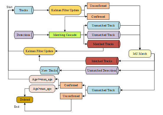
The specific flowchart of Deep Sort is shown in Figure 5, and the core process combines prediction, observation and update using Sort. In the framework, the state of transportation vehicles is modeled as, \[\label{rindEQ__1_}\tag{1} x=[u,v,s,r,u',v',s']^{T},\] where \((u,v)\) denotes the horizontal and vertical coordinates of the vehicle’s anchor frame, \(s\) denotes the area of the anchor frame, \(r\) is the width-to-height ratio of the anchor frame, and \(u',v',s'\) is the Kalman filtered predicted value of the horizontal position, vertical position, and area of the anchor frame, respectively.
Representation Information Correlation
Deep Sort introduces the representation information association method for the recognition of moving vehicles, which mainly adopts the target re-identification to extract the target’s appearance features for nearest neighbor matching during the real-time target tracking process.
Representation information association for each detection block \(d_{j}\) appearance feature extraction is carried out through the re-recognition network, the extracted target detection frames are unified to find out its feature vector \(r_{j}\). tracker is the same way to go for appearance feature extraction, for each tracking target to build a gallery, used to store each tracking target associated with the success of the last 100 frames of the feature vector. Then these 100 feature vectors are used to calculate the minimum cosine distance with the feature vectors of the current frame detection result, which is calculated as, \[\label{rindEQ__2_}\tag{2} d^{(2)} (i,j)=\min \left\{1-r_{j}^{T} r_{k}^{(i)} |r_{k}^{(i)} \in R_{i} \right\},\] where, \(d^{(2)} (i,j)\) represents the minimum cosine distance obtained by calculating the result by calculating, \(r_{j}^{T} r_{k}^{(i)}\) represents the cosine similarity, the cosine distance is 1 minus the cosine similarity to get, \(r_{k}^{(i)}\) represents the threshold \(t^{(2)}\) is set to 0.2, and this threshold is obtained by training individually, and if the cosine distance obtained by calculating is less than the threshold, then the association is successful. The mathematical formula is, \[\label{rindEQ__3_}\tag{3} b_{i,j}^{(2)} =\left[d^{(2)} (i,j)\le t^{(2)} \right].\] According to the above mentioned Marginal and Minimum Cosine Distance solving process both should be as small as possible. The combined match is obtained by fusing both representational and motion information and weighting them. Then \[\label{rindEQ__4_}\tag{4} c_{i,j} =\lambda d^{(2)} (i,j)+(1-\lambda )d^{(2)} (i,j),\] where \(\lambda\) is the hyperparameter that mainly controls the integrated matching correlation.
Implementation of Kalman filter algorithm
Kalman filter is a kind of efficient auto-regressive filter, by weighting the actual value and the predicted value to obtain the optimal state estimation, which can well deal with the information with noise interference, in this paper, Kalman filter is used to predict the state of the component transportation vehicle in the next moment according to the movement and position information of the component transportation vehicle in a certain moment. \[\label{GrindEQ__5_}\tag{5} \begin{array}{c} {\left\{\begin{array}{l} {x_{t} {'} =Cx_{t-1} +Du_{t-1} } \\ {P_{t} {'} =CP_{t-1} C^{T} +Q} \end{array}\right. } \end{array}\] \[\label{GrindEQ__6_}\tag{6} \left\{\begin{array}{l} {K_{t} =P_{t} {'} H^{T} \left(HP_{t} {'} H^{T} +R\right)^{-1} }\\ {x_{t} =x_{t} {'} +K_{t} \left(z_{t} -Hx_{t} {'} \right)}\\ {P_{t} =\left(1-K_{t} H\right)P_{t} {'} } \end{array}\right.\] Eqs. 5 and 6 are the formulas for the prediction and updating phases, respectively, where \(x_{t-1}\) and \(x_{t}\) are the updated results at the \(t-1\) and \(t\) moments, respectively, \(x_{t} {'}\) is the state estimate at the \(t\) moment, \(P_{t-1}\) and \(P_{t}\) are the covariance of the results \(\left(x_{t-1} And\; x_{t} \right)\); at the \(t-1\) and \(t\) moments, respectively, indicating the degree of uncertainty, \(P_{t} {'}\) is the covariance of the state estimate \(x_{t} {'}\) at the \(t\) moment, is the transformation matrix, is the Kalman filter increment, is the state transfer matrix, and is the covariance of the system, indicating the degree of uncertainty, and is the transformation matrix and the actual matrix. covariance, \(H\) is the transformation matrix, which is responsible for transferring the MMM-dimensional measurements to the \(n\) dimension, \(z_{t}\) is the measurement value, \(K_{t}\) is the Kalman filter increment, \(C\) is the state transfer matrix, \(Q\) is the covariance of the system, which indicates the error between the transformation matrix and the actual value, \(D\) is the matrix that transforms the inputs to the state, and RRR is the measurement noise covariance, which is the residual of the actual and predicted values.
Kalman filtering is to use Eq. 5 to obtain the a priori estimate, and then correct the a priori estimate by Eq. 6 , and finally the optimal estimation state can be derived by the cycle of Eq. 5 and Eq. 6 to calculate each other.
In this paper, the input image sequence is set to 20 frames per second, and the time of each Kalman filtering cycle is 50 ms. Since the interval between two adjacent frames in the sequence is short, and the position of the component transportation vehicle changes little, it can be assumed that the component transportation vehicle is in uniform linear motion during this time. In this paper the state of Kalman filtering is defined as, \[\label{rindEQ__7_}\tag{7} X_{k} =\left(x_{s}^{k} ,y_{x}^{k} ,x_{v}^{k} ,y_{v}^{k} \right),\] where \(\left(x_{s}^{k} ,y_{x}^{k} \right)\) denotes the position of the component transportation vehicle in the \(x\) and \(y\) axes at the moment of \(t_{k}\), \(\left(x_{v}^{k} ,y_{v}^{k} \right)\) denotes the velocity of the component transportation vehicle in the \(x\) and \(y\) axes at the moment of \(t_{k}\), and the observed state vector is defined as \(Z_{k} =\left(x_{w}^{k} ,y_{w}^{k} \right)\), which denotes the observed position of the component transportation vehicle. Since the component transportation vehicle is doing uniform linear motion in the same time interval, let \(\Delta t\) denote \(\Delta t=t_{k} -t_{k-1}\), then the state transfer matrix \(C\) is, \[\label{rindEQ__8_}\tag{8} C=\left[\begin{array}{cccc} {1} & {0} & {\Delta t} & {0} \\ {0} & {1} & {0} & {\Delta t} \\ {0} & {0} & {1} & {0} \\ {0} & {0} & {0} & {1} \end{array}\right]\] The transformation matrix H is, \[\label{rindEQ__9_}\tag{9} H=\left[\begin{array}{llll} {1} & {0} & {0} & {0} \\ {0} & {1} & {0} & {0} \end{array}\right].\] Next, the motion state estimation can be carried out according to the characteristic points of the component transportation vehicle, and the specific prediction process is as follows: after identifying the characteristic points of the component transportation vehicle, delimit the search area of the characteristic points, detect the position \(\left(x_{s}^{k} ,y_{x}^{k} \right)\) of the component transportation vehicle in the area, input this coordinate into the Kalman filter, update the state of the Kalman filter, and finally predict the position of the component transportation vehicle in the next moment according to the filtered state.
The BeiDou navigation system (BDS) realizes accurate positioning by means of GNSS signals, which generally consist of satellite navigation messages and ranging codes, modulated on a carrier wave by a certain modulation method, and sent to its service area through a high-gain antenna on the satellite. The ranging code is generally two kinds, respectively C/A code and P code, both are pseudo-random codes. The pseudorange is calculated by C/A code and P code, and the method of localization is called code pseudorange localization method. The carrier wave that carries the navigation information is a periodic sine wave, so the distance can be measured according to its phase variation, so as to carry out three-dimensional localization, which is called the phased pseudorange localization method.
First assume that at the moment \(t_{0}\), the carrier phase received by the receiver is \(\varphi _{r} \left(t_{0} \right)\) and the carrier phase transmitted by the satellite is \(\varphi _{s} \left(t_{0} \right)\), then the carrier phase difference between the satellite and the receiver at both places is, \[\label{GrindEQ__10_}\tag{10} \Phi _{i} {'} \left(t_{0} \right)=\varphi _{s} \left(t_{0} \right)-\varphi _{r} \left(t_{0} \right).\] Satellite carrier signal is a periodic sine wave, there is no identification labeling, we can only determine its less than a full week of the fractional part of \(\Delta \varphi _{0}\), the carrier phase of the number of full weeks N can be obtained by the receiver continuous full week counting.
The carrier phase difference can be written as, \[\label{GrindEQ__11_}\tag{11} \Phi _{i}^{J} \left(t_{0} \right)=\varphi _{s} \left(t_{0} \right)-\varphi _{r} \left(t_{0} \right)=N_{i}^{j} \left(t_{0} \right)+\Delta \varphi _{0}.\] One cycle of the carrier corresponds to a distance of \(\lambda\), and the pseudo-distance is: \[\label{GrindEQ__12_}\tag{12} \rho _{i} {'} =\lambda \left(\varphi _{s} -\varphi _{r} \right)=\lambda \left(N_{0} {'} +\Delta \varphi _{0} \right).\] Satellite in orbit, when the receiver continuously locks and receives the satellite carrier, the satellite movement caused by the phase difference increase in the whole week part of the \(Int\left(\varphi _{i} \right)\) can be measured by the whole week counter, at this time the observation equation is: \[ \begin{equation} \label{GrindEQ__13_}\tag{13} \rho {}_{i}^{j} = \lambda (\varphi _{s} -\varphi _{r}) \notag = \lambda [N_{0}^{j} +\text{Int}(\varphi _{i})+\Delta \varphi _{i}] \notag = \sqrt{(X^{j} -X)^{2} +(Y^{j} -Y)^{2} +(Z^{j} -Z)^{2}} \end{equation} \]
According to the above settlement of the position coordinates of the transportation vehicle, it can be seen that the single satellite positioning will be greatly reduced in accuracy, and will be interfered with by external factors for the high-precision positioning requirements. In order to reduce the interference of various external factors, this paper adopts BeiDou high-precision differential positioning technology for the accurate positioning of assembly building structure components transportation vehicles.
The positioning principle of differential positioning technology is to establish a reference station for ground observation, the position coordinates of the reference station are known and accurate, the satellite is used to locate the reference station, and the receiver receives the satellite positioning coordinates of the reference station. The known precise coordinate value and satellite coordinate value comparison, the difference between the value will become a correction value, for positioning error correction, after this correction, differential positioning technology can eliminate most of the public error, positioning accuracy can reach the centimeter level.
The exact coordinates of the reference station are \(\left(X_{0} ,Y_{0} ,Z_{0} \right)\), and the satellite positioning coordinates of this reference station received by the receiver are \((X,Y,Z)\), and the corrected value of the two is solved as \(\left(\Delta X,\Delta Y,\Delta Z\right)\), i.e., \[\label{rindEQ__14_}\tag{14} \left\{ \begin{array}{l} {\Delta X=X_{0} -X} \\{\Delta Y=Y_{0} -Y} \\ {\Delta Z=Z_{0} -Z} \end{array}\right.\] The uncorrected satellite coordinates on the user side are \(\left(X_{u}^{1} ,Y_{u}^{1} ,Z_{u}^{1} \right)\),The coordinates after adding the correction \(\left(\Delta X,\Delta Y,\Delta Z\right)\) are \(\left(X_{u}^{0} ,Y_{u}^{0} ,Z_{u}^{0} \right)\), i.e., \[\label{rindEQ__15_}\tag{15} \left\{ \begin{array}{l} {X_{u}^{0} =X_{u}^{1} +\Delta X} \\{Y_{u}^{0} =Y_{u}^{0} +\Delta Y} \\{Z_{u}^{0} =Z_{u}^{1} +\Delta Z} \end{array}\right.\] Since the position of the user end changes during the transmission of the corrected value, the position change is accounted for as an effect, and the final satellite coordinates of the user end after correction are \(\left(X_{u} ,Y_{u} ,Z_{u} \right)\), i.e., \[\label{rindEQ__16_}\tag{16} \left\{\begin{array}{l} {X_{u} =X_{u}^{1} +\Delta X+\frac{d\left(X_{u}^{1} +\Delta X\right)}{dt} \left(t-t_{0} \right)} \\ {Y_{u} =Y_{u}^{1} +\Delta Y+\frac{d\left(Y_{u}^{1} +\Delta Y\right)}{dt} \left(t-t_{0} \right)} \\ {Z_{u} =Z_{u}^{1} +\Delta Z+\frac{d\left(Z_{u}^{1} +\Delta Z\right)}{dt} \left(t-t_{0} \right)} \end{array}\right.\] Using BeiDou high-precision differential positioning technology, it can make the assembled building structure component transportation vehicle get the correction number in real time to correct the position of its own positioning, which is obtained and sent by a stationary reference station, and the component transportation vehicle corrects the test result through the joint calculation of the correction number and its own observation value, so as to obtain a high positioning accuracy.
Studying the tracking management problem of structural components of assembled buildings can realize the fine management of prefabricated components, improve the production efficiency of assembled building construction, and use the technology in the whole life cycle of prefabricated components to make the construction level of digitalization, informatization, and industrialization of assembled buildings continuously improve, and help the transformation and upgrading of the construction industry. This chapter focuses on the simulation test of tracking and positioning technology in the transportation process of structural components of assembly buildings, so as to verify the effectiveness of the technology proposed in this paper.
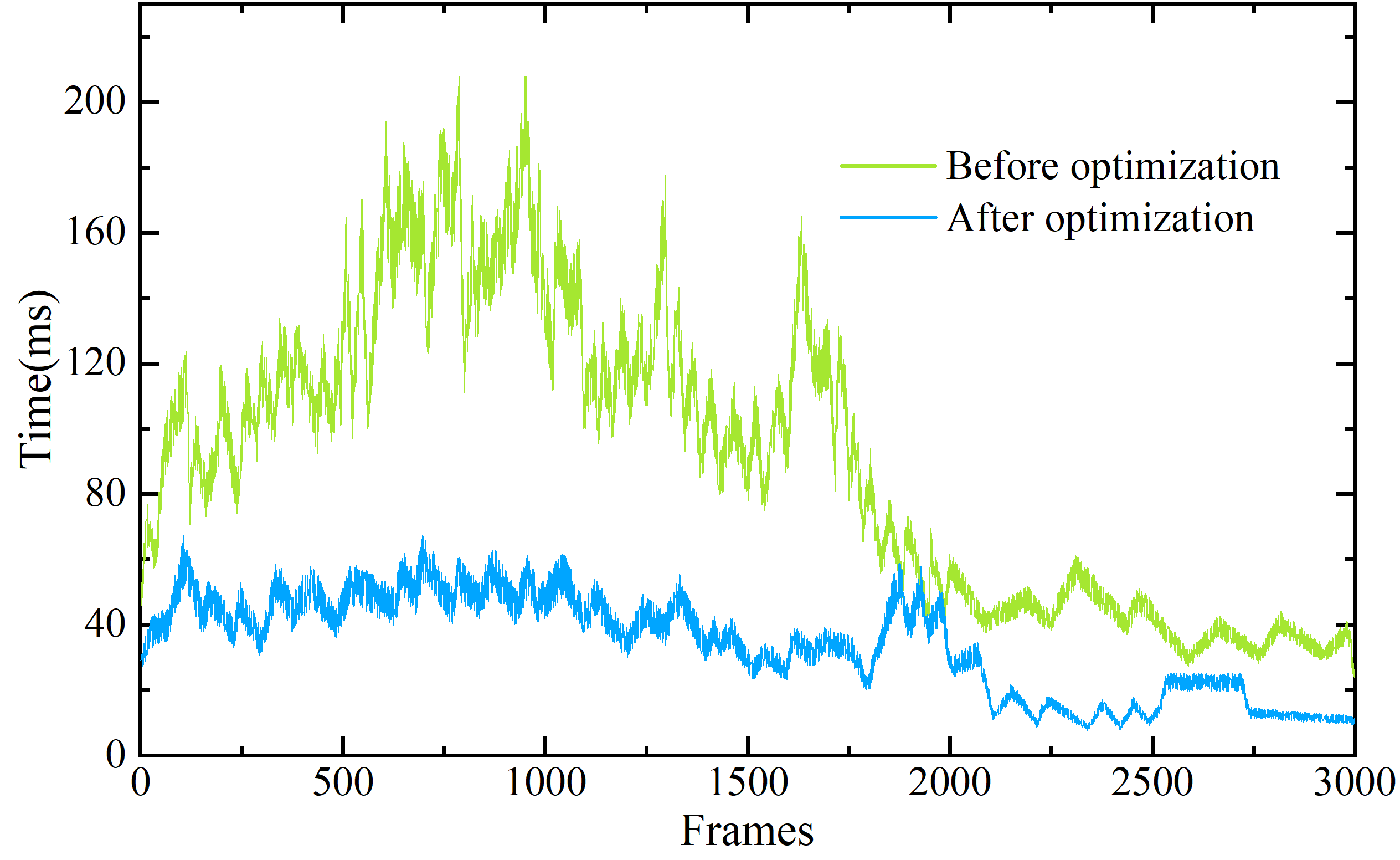
In Deep Sort multi-target tracking algorithm, this paper introduces the method of characterization information association to enhance the detection efficiency of the detection frame to be tracked, in order to verify the optimization effect of this method on Deep Sort multi-target tracking algorithm, this paper selects the intersection surveillance video that must be passed by the vehicles of assembled components transportation in a certain city as a validation object, and selects the FPS as an evaluation index, which refers to the time of the algorithm processing video The time of each frame speed. Figure 6 shows the optimization effect of Deep Sort multi-target tracking algorithm.
From the Figure 6, it can be seen that the average tracking time of the Deep Sort multi-target tracking algorithm before the introduction of the representation information association is 90.45ms in 3000 frames, while the average tracking time of the algorithm after the optimization is 34.19ms.The average FPS of the original Deep Sort multi-target tracking algorithm is about 8, while the average FPS of the tracking algorithm after the optimization is increased to about 45, and the average FPS of the tracking algorithm after the optimization is about 10. The average FPS of the original Deep Sort multi-target tracking algorithm is about 8, while the average FPS of the tracking algorithm after optimization is about 45, which is a 4.625 times increase. This shows that the introduction of representation information management in the algorithm can realize the meaningful comparison of vehicles in the surveillance video, and the method can track and match only the transportation vehicles that tend to be in a specific area, and give up the tracking and delete their corresponding track IDs if they exceed the area, reduce the number of existing tracks in the Tracker to reduce the amount of matching calculations, reduce the matching time for the number of detected frames, and improve the tracking and matching of the vehicles transporting the components of assembled buildings. building components transportation vehicle tracking and matching.
In order to further analyze the effectiveness of this paper’s method in the vehicle transportation of structural components of assembled buildings, this subsection uses the improved Deep Sort multi-objective tracking algorithm and the original Deep Sort algorithm to conduct comparative experiments on the MOT20 dataset. Ten evaluation videos from the MOT20 dataset are selected for experimental statistics, resulting in the real-time comparison results of the improved Deep Sort algorithm as shown in Table 1.
From the real-time comparison results, the improved Deep Sort multi-target tracking algorithm obtains lower FPS under different frame numbers of video sequences, and the average FPS of each video sequence in the table is 8.196 frames/ms, while the original Deep Sort multi-target tracking algorithm obtains an average FPS of 9.729 frames/ms, which is an improvement of the improved algorithm’s real-time performance compared with the original algorithm. is improved compared with the original algorithm. This also further verifies the effectiveness of this paper’s method for multi-target detection of transportation vehicles under different video sequences, which can better realize the real-time tracking of the transportation of structural components of assembled buildings, and provide a reference for the rational planning and scheduling of structural components of assembled buildings.
| Cycle tests | Frame | Original-duration(ms) | Improve-duration(ms) | Original-FPS | Improve-FPS |
|---|---|---|---|---|---|
| MOT20-1 | 400 | 32.152 | 40.518 | 12.44 | 9.87 |
| MOT20-2 | 1000 | 115.483 | 136.452 | 8.66 | 7.33 |
| MOT20-3 | 1248 | 134.362 | 157.623 | 9.29 | 7.92 |
| MOT20-4 | 565 | 68.426 | 75.931 | 8.26 | 7.44 |
| MOT20-5 | 678 | 75.448 | 83.195 | 8.99 | 8.15 |
| MOT20-6 | 950 | 104.621 | 125.748 | 9.08 | 7.55 |
| MOT20-7 | 700 | 81.663 | 92.153 | 8.57 | 7.60 |
| MOT20-8 | 860 | 86.479 | 98.475 | 9.94 | 8.73 |
| MOT20-9 | 1200 | 129.157 | 151.438 | 9.29 | 7.92 |
| MOT20-10 | 450 | 35.236 | 47.625 | 12.77 | 9.45 |
The Deep Sort multi-target tracking algorithm is the matching of the trajectory and the value of the curve of the track and the curve of the curve. But in the actual application scenario, because the motion of the vehicle cannot be regarded as a uniform motion, the distance of the motion information is considered as a rough estimate, which is usually used to filter the mismatch of the position of the position. In the latter study, we can improve the reknowledge module by combining the vehicle positioning.
For the multi-target tracking algorithm proposed in this paper for assembly building structural components transportation vehicles, this paper adopts the KITTI dataset to validate the experimental results, and the main evaluation indexes include multi-target tracking precision (MOTP), multi-target tracking accuracy (MOTA), IDS denotes the number of times the target’s label has changed in the t moment, MT is the ratio of trajectories most of the target is tracked to, and ML is the ratio of trajectories most of the target is followed and lost. s percentage of trajectories mostly followed and lost, and FRAG is the number of disconnections of hypothetical trajectories in the algorithm output. A variety of target tracking algorithms are selected as comparison algorithms, and the comparison results of tracking performance of component transportation vehicles under different algorithms are shown in Table 2.
From the algorithm comparison results, the main indicator of multi-objective tracking quality, MTOP, of this paper’s method is higher than all the comparison methods, with an MTOP value of 86.47%, which is 4.98 percentage points higher than that of the best-performing RMOT algorithm. This reflects that the method in this paper has good accuracy in tracking vehicles transporting components of assembled building structures and can accurately obtain the information of component transportation vehicles from the traffic flow. The IDS and FRAG obtained by this paper’s method are 1247 and 2562 times respectively, which indicates that this paper’s method performs poorly on the hopping trajectory of component transportation vehicles and needs to be optimized to better obtain the transportation hopping trajectory. The MT and ML obtained by this paper’s method in the experiment are 31.45% and 6.02% respectively, which are higher than those of the comparison algorithms, which reflects that this paper’s algorithm can still realize accurate multi-objective tracking of component transportation vehicles under the environment of obstruction and various noises, and provide vehicle operation trajectories for the realization of the reasonable scheduling of structural components in assembled buildings, so as to realize the high-quality development of assembled buildings.
| Method | MOTA(%) | MOTP(%) | IDS | MT(%) | ML(%) | FRAG | Runtime |
|---|---|---|---|---|---|---|---|
| Ours | 63.53 | 86.47 | 1247 | 31.45 | 6.02 | 2562 | 3.15ms |
| NOMT | 56.89 | 78.78 | 21 | 34.07 | 27.75 | 153 | 93.45ms |
| RMOT | 56.64 | 81.49 | 215 | 46.28 | 13.79 | 486 | 26.28ms |
| LP-SVM | 61.51 | 76.75 | 36 | 55.14 | 22.11 | 431 | 55.65ms |
| NOMT | 52.09 | 80.27 | 28 | 38.53 | 20.58 | 258 | 96.73ms |
| SSP | 63.44 | 77.83 | 11 | 36.85 | 25.08 | 772 | 63.26ms |
| SCEA | 57.86 | 76.32 | 18 | 54.71 | 16.55 | 653 | 51.25ms |
| mbodSSP | 62.72 | 80.96 | 3 | 44.36 | 21.23 | 578 | 11.46ms |
| Point3DT | 54.03 | 76.45 | 152 | 40.79 | 28.95 | 462 | 51.62ms |
| TBD | 60.95 | 75.68 | 33 | 53.85 | 32.04 | 515 | 102.17ms |
In order to verify the effectiveness of the tracking and localization technology for structural components of assembled buildings given in this paper, this paper carries out static and dynamic identification and localization experiments for structural components of buildings in different scenarios. This paper first carries out the static positioning experiments of building structural components in the laboratory, selecting bolts, reinforcement bars, corner connectors and screwdrivers as the positioning objects, measuring the real 3D spatial coordinates of each component using a tape measure, and then comparing them with the spatial coordinates obtained by the differential positioning algorithm. In this paper, absolute error (Error), relative error (RE) and offset rate (RS) are chosen as evaluation indexes, and the results of static positioning experiments are shown in Table 3.
From the comparison results of static positioning experiments, the shape of the building structural components of the steel bar type is more special, and its positioning coordinate error is the largest, and its coordinate error in X, Y and Z axes is 0.06m, and its absolute error is 0.06m, and the relative error is 1.58%. The four kinds of building structural components in addition to the screwdriver’s offset rate is less than 0.9, the rest of the components positioning offset rate is more than 1.2, which indicates that the positioning spatial coordinates do not fall on the building structural components, and there is still a little offset, but overall the absolute error of positioning is less than 0.5m, which indicates that the method of this paper can realize the high-precision positioning of the transportation of the assembled building structural components.
| Member | Axes | Actual value(m) | Detection value(m) | Coordinate error(m) | Error(m) | RE | RS |
|---|---|---|---|---|---|---|---|
| Bolt | X | 1.93 | 1.91 | 0.02 | 0.05 | 0.76% | 1.42 |
| Y | 2.87 | 2.86 | 0.01 | ||||
| Z | 0.65 | 0.61 | 0.04 | ||||
| Rebar | X | 1.28 | 1.34 | 0.06 | 0.06 | 1.58% | 1.28 |
| Y | 2.59 | 2.65 | 0.06 | ||||
| Z | 0.08 | -0.02 | 0.06 | ||||
| Screwdriver | X | 1.24 | 1.29 | 0.05 | 0.05 | 0.43% | 1.39 |
| Y | 1.98 | 1.93 | 0.05 | ||||
| Z | 0.03 | 0.07 | 0.04 | ||||
| Angle connector | X | 1.85 | 1.81 | 0.04 | 0.04 | 0.65% | 0.72 |
| Y | 1.97 | 1.92 | 0.05 | ||||
| Z | 0.01 | 0.04 | 0.03 |
Traditionally, the method of the method of the component of the assembly building component is based on the genetic algorithm of the deformation contour line tracking, which is based on the genetic algorithm to optimize the adaboost strong prediction model of bp neural network and the calculation of the horizontal cross section of the cloud data. The results of the results show that the deformation contour lines and the adaboost method are basically the same as the intermediate location values in the early period of monitoring, but they are phased out in the later stages of monitoring, and they are different from the real values. The point cloud data calculation method is compared to the actual value of the medium and later stages. In this paper, the overall variation of the method is the smallest difference between the total variation and the real value, and the data parameters can be analyzed accurately and the results are accurate.
In order to further verify that the method of this paper can still be accurately positioned during the transportation of structural components of assembled buildings, this paper selects the corner connector of the component as the experimental object, and uses the experimental platform of the overhead crane to transport it from A to B. After the crane opens the anti-swing mode, the tensile sensor on the platform can accurately measure the real position of the crane trolley at a certain moment, and the trolley’s position can reflect the actual position of the material in the case of a swing angle of 0.7\(\mathrm{{}^\circ}\) or less, and the actual value is compared with the results of the positioning algorithm in this paper. Figure 7 shows the results of the displacement comparison between the detected value and the real value in the XY direction.
From the results of the comparison between the detected value and the real value in X-axis and Y-axis, the maximum error in X- and Y-direction is in the process of lifting and transferring at the beginning of the movement and stopping the movement of the link, taking into account the error caused by the inertia of 0.03m, the actual maximum error is 0.37m. After the algorithm running time is more than 10s, the detected value and the real value derived from the method of this paper tends to stabilize, the real value and the detected value in the direction of Y-axis remain at 1.91%. The true value in the Y-axis direction is maintained at about 1.91m, and the true value in the X-axis direction is maintained at about 1.59m. The results based on the BeiDou high-precision differential positioning algorithm are consistent with the real-time true position results obtained by the tensile sensors, with a slight deviation at the start point and the end point due to inertia. The main reason is that although the crane opens the open-loop anti-swing mode, which can ensure that the swing angle is within 0.7\(\mathrm{{}^\circ}\), it still can’t completely eliminate the swing, so there will be a small deviation in the actual position of the crane and the crane trolley. This shows that the method in this paper can still realize the high-precision positioning of structural components of assembled buildings even under dynamic environment, and can better understand the specific position of structural components in the transportation process, which can provide a reference for the scheduling of assembled building components.

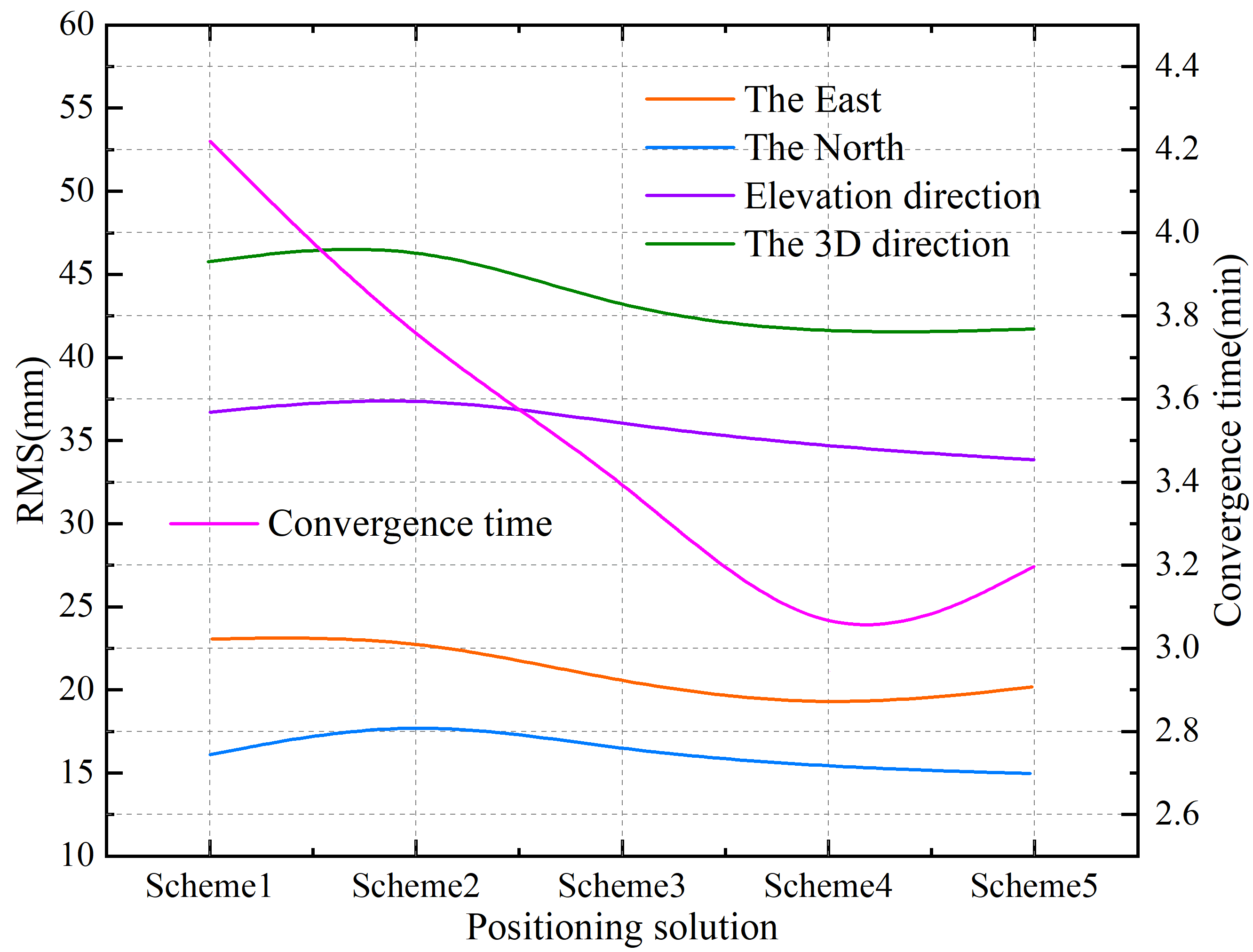
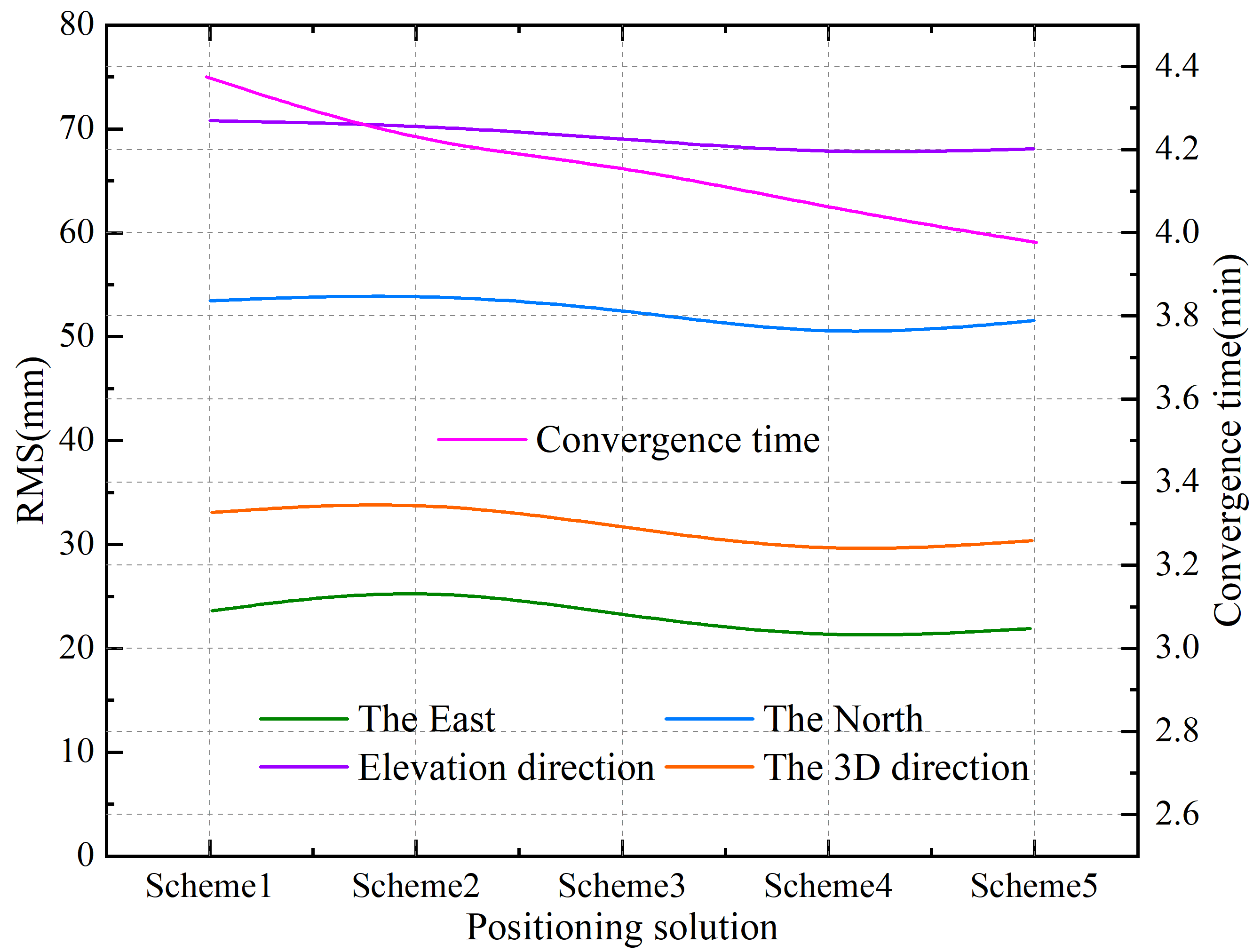
In order to further validate the accuracy and usability of this paper’s method in tracking and localization of structural components in assembled buildings, this paper selects 100 ground-based continuous tracking station data of structural component transportation vehicles between a distribution station and a construction site to solve the coordinates of the component transportation vehicles with a single GPS (Scheme 1), BDS-2/GPS (Scheme 2), BDS-3/GPS (Scheme 3), BDS-3/without estimation of the inter-BDS ISB (Scheme 4), and BDS-3/BDS-2/GPS without estimation of the inter-BDS ISB (Scheme 5). BDS-2/GPS combination (Scheme 4), and BDS-3/BDS-2/GPS with estimation of inter-BDS ISB (Scheme 5) are five schemes to compare the accuracy and convergence time of coordinate solving for component transportation vehicles. Taking the processed BeiDou navigation coordinates as the reference truth value, the convergence time and RMS of positioning residuals of the static and dynamic vehicle positioning coordinate solving results are counted separately, resulting in the positioning accuracy and convergence time shown in Figure [f8]. Among them, Figure [f8] (a) and (b) show the static and dynamic positioning accuracy and convergence time, respectively, and the elevation direction, north direction, east direction and 3D direction of vehicle coordinates are selected for the RMS solving of positioning residuals, respectively.
As can be seen from the Figure [f8], the average convergence time of static and dynamic solving is lower than 3.49min and 4.14min respectively, of which the shortest average convergence time of static and dynamic solving are scheme 4 and 5 respectively, and the average convergence time of static and dynamic vehicle position coordinate solving is 3.17min and 3.58min respectively for schemes 1-5, and the overall performance of the static solving mode is better than the dynamic mode solving, with better localization accuracy and convergence speed than the dynamic mode solving. The overall performance shows that the positioning accuracy and convergence speed of the static solving mode are better than that of the dynamic solving mode, and the convergence time is shortened with the increase of the number of satellites involved in the solving, which is strongly correlated with the strength of the model. Comparing the results of real-time and post-processing solving, the results show that the convergence time of real-time dynamic position coordinate solving for component transportation vehicles is slightly prolonged due to the limitation of satellite orbits and accuracies, but the difference in convergence time between post-processing and real-time solving is controlled within 5 min. The average convergence time difference between real-time and post-processing modes in static solving mode is 4.23min, and the average convergence time difference between post-processing and real-time solving is only 2.87min. The difference between post-processing and real-time processing is large, and there is a certain difference between real-time and post-processing solving accuracy, in general, the BeiDou high-precision differential positioning technology given in this paper can realize high accuracy real-time static and dynamic position coordinates of real-time component transportation vehicles. Overall, the BeiDou high-precision differential positioning technique given in this paper can realize high-precision real-time static and dynamic position coordinate solving, which can provide support for the accurate positioning of structural components of assembled buildings.
Through the simulation analysis of the assembly building components, the feasibility of BIM technology is verified. The application of this paper is applied to the practical case, and discusses its application in environmental protection and sustainable development.
Based on the project of the park avenue of a construction group, the design of each module is formed by the summary of the pilot project. Using BIM to model 3D simulation, the mechanical and electrical pipeline is also studied to deepen the layout, the centralized number and location. The pipeline and support science is divided and presented, and the mechanical and electrical integrated system grade products are formed by the assembly of the pipeline, the module transportation and the on-site assembly.
The successful implementation of this method has achieved remarkable economic, social and environmental benefits, and developed a mature construction process. The assembly type construction technique is used in the pipeline well and the basement tube, through standard design, standard drawing, modular prefabrication, single-type distribution, fast and high efficiency assembly construction, to achieve the goal of quality reduction, safe and efficient, energy conservation and environmental protection.
In this study, an efficient and accurate component tracking and localization system is successfully developed through in-depth research and several experimental verifications. The system combines the advantages of information technology and BeiDou high-precision differential positioning technology, and provides a practical technical solution for solving the key problems in the construction process of assembled buildings. The implementation of the system significantly improves the construction efficiency.
Through the optimized Deep Sort multi-target tracking algorithm, efficient tracking of assembly building component transportation vehicles was achieved, reducing the tracking time from 90.45ms to 34.19ms, an improvement of about 4.625 times. This improvement directly leads to an increase in construction efficiency of about 40%, especially in complex construction environments, where rapid tracking and localization of components reduces a large amount of labor and time costs. By implementing the present technology, logistics costs during construction are reduced by approximately 30%. Accurate tracking and positioning reduces the need for large amounts of temporary storage space, while reducing repeated handling and rework due to misplacing and misassembling. Combined with BeiDou’s high-precision differential positioning technology, this system also shows remarkable results in construction site safety management. By reducing on-site confusion and mishandling, the accident rate was reduced by about 20%.
The developed tracking and positioning technology for structural components of assembled buildings not only improves construction efficiency and accuracy, but also shows great potential in cost control, safety management, and environmental protection. With further optimization and wider application of the technology, it is expected to trigger wider changes in the construction industry and make significant contributions to the industry’s sustainable development.
From the perspective of data flow, the component tracking technique that is involved in this paper can be divided into data collection and number according to the management of two points, the former is mainly measured by measurement technology, which is mainly based on architecture and computer graphics. This paper focuses on the applicability of the existing measurement technology, rather than the new measurement technology. In the future, we can cooperate with the measurement technology plan to develop the appropriate measurement method. In theory, the whole life cycle of assembly buildings not only contains the design and construction of the components, but also the maintenance and demolition. The experiment is still ongoing in the operation maintenance phase and the demolition recovery phase, which is also the reason for this failure to go deep into this level and the next direction.